Information Flow Overview
Phase 1 of the Setup Journey. Build your mental model of the data path before installing software or plugging in hardware.
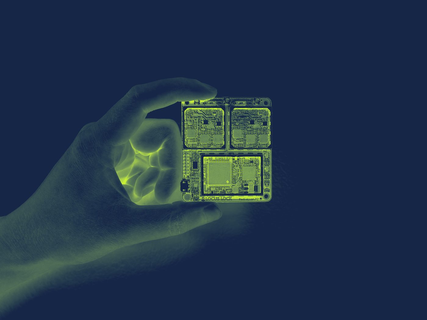
LEO100 is built for real-time embedded applications. It produces PNT solutions, raw observables, and ancillary data entirely in software on your host computer, with no separate hardware receiver in the loop. That lets it drop cleanly into flight controllers, autopilots, autonomy stacks, and other on-vehicle compute.
Knowing how a GNSS signal becomes a position fix on that host is what makes every later choice obvious instead of arbitrary: which output to enable, where to put middleware, and what to record for debugging. Trace the full path below.
The full data path split by component. Select a function within any component to see what happens there.
Captures the faint GNSS RF signals broadcast by satellites across the L1, L2, and L5 bands and passes them to the RF front end over coax. Antennas are not included with LEO100, but are required for live operation.
Recommended antennas →The triple-frequency RF front end. It conditions and digitizes the analog antenna signal so software can process it, in three steps.
A low-SWaP, real-time software-defined GNSS receiver that runs entirely on your host CPU. It processes the digital IF samples in a continuous loop, producing a PVT solution and configurable data outputs.
PpRx Display reference →――――――――――――― GRID: General Radionavigation Interfusion Device ――――――――――――
RRT: 0 weeks 222.2 seconds Build ID: 4917
ORT: 1490 weeks 146234.0 seconds
―――――――――――――――――――――――――――――――――――――――――――――――――――――――――――――――――――――――――――
CH TXID Doppler BCP PR C/N₀ Az El CS
(Hz) (cycles) (meters) (dB-Hz) (deg) (deg)
―――――――――――――――――――――――――――― GPS_L1_CA_PRIMARY ――――――――――――――――――――――――――――
1 5 -3700.2 12948972.2 24923426.7 40.0 41.4 7.3 7
2 14 -2283.5 12629722.8 21977305.3 49.3 110.9 41.4 7
3 16 3269.5 11395962.4 22297488.0 48.9 191.7 34.2 7
4 20 1337.7 11818247.0 22173947.0 49.4 298.4 36.6 7
5 22 -3804.2 12976976.9 25178762.7 38.7 164.5 3.9 7
6 29 1506.3 11785134.9 24108553.8 44.2 85.7 16.4 7
7 30 -2874.0 12758476.0 22460802.6 48.2 49.2 30.5 7
8 31 -330.1 12195832.6 20504836.0 54.5 347.7 76.0 7
9 32 263.7 12057205.4 21387833.5 52.9 274.0 54.2 7
10 -- --------- ------------- ----------- ---- ----- ---- -
―――――――――――――――――――――――――――― GPS_L2_CL_PRIMARY ――――――――――――――――――――――――――――
1 29 1173.8 -219300.8 24108560.8 40.3 85.7 16.4 6
2 31 -257.3 42503.2 20504848.1 54.4 347.7 76.0 6
3 -- --------- ------------- ----------- ---- ----- ---- -
―――――――――――――――――――――――――――― Standard Solution ――――――――――――――――――――――――――――
PX: 1101966.84 PY: -4583482.27 PZ: 4282236.05 δtR: 12584.29
VX: 0.00 VY: 0.00 VZ: 0.00 δtRdot: 8.16
Hσ: 0.81 Vσ: 1.22 εν: 0.36
――――――――――――――――――――――――――――――― IMU Data ―――――――――――――――――――――――――――――――――
AX: 0.43 AY: 5.40 AZ: 8.18
ωBX: -0.28 ωBY: -0.13 ωBZ: 0.08
RRT: 79.992 Temp: 37.0
―――――――――――――――――――――――――――――――――――――――――――――――――――――――――――――――――――――――――――Your application running on the host computer, such as an autopilot, autonomy stack, or logger. It decodes the output stream and uses the solution however your platform needs.

You're done with Phase 1 when: you can sketch this data path and name which LEO100 component owns each stage. Next up is Phase 2, Software Installation.